Preplanning is used in all aspects of the horizontal directional drilling (HDD) process. Whether it is planning the jobsite layout or the restoration, there should be a plan for it. One area that is commonly overlooked is creating a rod-by-rod bore plan.
Have you ever wondered how you’re going to navigate through a congested area? Or have you had to pull rods back during the pilot bore? Creating a bore plan gives you specific depths to follow and allows you to efficiently execute the pilot bore. This also requires some quick math to create a bore plan on the jobsite. If you aren’t good at math, don’t be worried.
Now let’s talk about how exactly you create an HDD bore plan.
Before you begin…
Before creating the proposed bore plan, it’s important to know the location and depth of existing utilities and jobsite parameters. Knowing this helps you understand what to avoid and where to bore. This may include the clearance needed around utilities and the desired depth of the new utility. If reaming is required, make sure to increase the utility clearance during the planning process.
“It’s also important to understand the allowable percent pitch per rod, HDD tooling and ground conditions, along with the bend radius of the product being installed,” explained Ben Hedrick, Vermeer training specialist. “HDD rods are designed to bend slightly, but if they’re overbent, even once, they can be damaged and result in premature failure.”
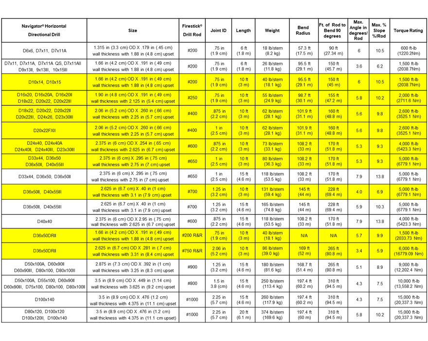
Here’s a chart that shows the Vermeer HDD machines and the drill rod specifications:
Calculating you rod-by-rod plan
For this example, we’re going to reference a D20x22 S3 Navigator® horizontal directional drill, which has 10-ft (3-m) rod and a maximum bend of 9.8%. Let’s round this up to 10% for the maximum pitch change to allow for some quick math.
Using this information and jobsite parameters, such as existing utilities and jobsite specifications, we can now start calculating a simple rod-by-rod plan on a piece of graph paper.
Here’s what we’ll be working from:
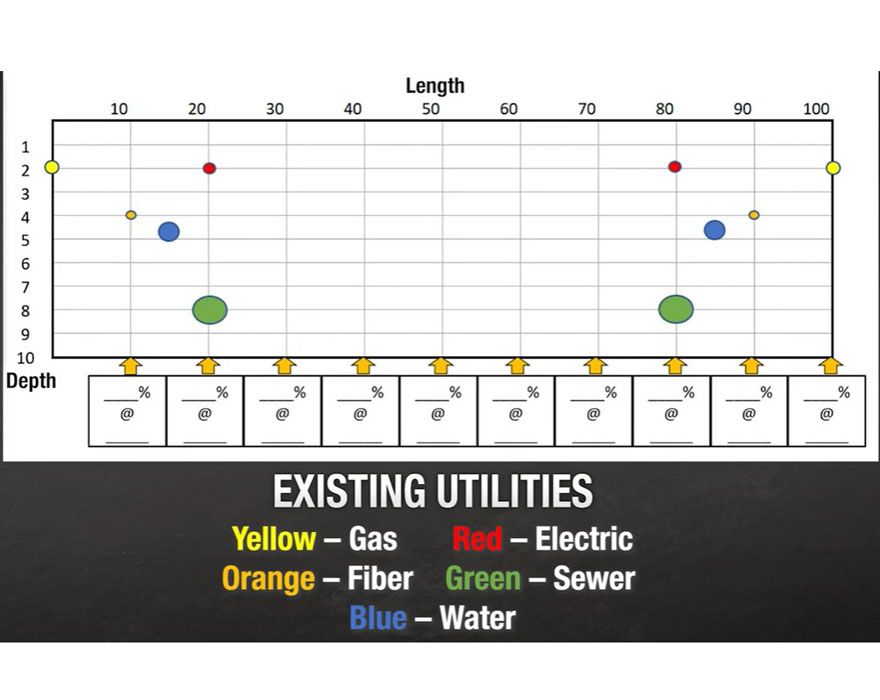
For this example, the math will be in feet. Our parameters are a 100-ft (30-m) long bore, an approximate depth of 5 ft (1.5 m) and maintaining 1.5-ft (.45-m) clearance around all utilities. An average drill setup on level ground will have the drill head position or angle sitting between -20% and -30%. For this reason, normally you would start this proposed bore plan with your first rod at -25%. To calculate the first rod depth, multiply the 10-ft rod by the current pitch of -25% (10 ft x -25% = x). This equals -2.5 ft (-0.8 m), which is the approximate depth change of the drill head once the full rod has been drilled into the ground.
Now you can draw the first rod on the graph starting at the corner of the graph paper and go down approximately 2.5 ft (0.8 m) and over 10 ft (3 m) and make a dock. This represents the approximate depth of the drill head at the completion of the first rod. You can also write out the predicted depth and pitch below to help you know where you’re at and how much you can change on the next rod. Since the drill head is at a -25% pitch, the maximum rod bend of 10% allows a change down to -35%, or up to a -15%, and anywhere in between.
Next, decide what depth you need to be at the end of rod two, then figure out what pitch will get you there. For example, to get to 4-ft-deep (1 m) at the end of the second rod, you’ll need to go 1.5 ft (0.5 m) deeper. If you multiply the 10-ft rod by -15%, it equals -1.5 ft. Now you know you need to change to -15% to be at 4 ft deep.
After you draw that rod, then you can write down your current depth and pitch. Now say that you want to be level at 5-ft-deep (2 m), which leaves two more rods to achieve that depth. On rod three, you’re going to change the pitch to a -10%, which will result in a 1-ft depth change, bringing the depth to 5 ft. Now, on the fourth rod, you can go to a 0% pitch and your depth will stay approximately at 5-ft deep. Knowing that it took four rods to get down to 5 ft and level, you’ll maintain a 0% pitch for rods five, six and seven.
Before exiting the ground, it is best practice to have your bore path entry and exit at approximately the same pitch angles. So that means on rod eight, you’ll start gradually coming up. Knowing that you want to be at 4 ft at the end of this rod, a depth change of 1 ft (0.3 m) is needed. To achieve this, you want to end this rod at a positive 10%.
For rod nine, you want to end at a depth of 2.5 ft. Having 1.5-ft depth change requires an ending pitch of positive 15%. The parameters of this bore were to exit the ground on the 10th rod. The current depth is 2.5 feet at a positive 15%. To exit the ground at the end of this rod, a 2.5-ft depth change is needed. A positive 25% pitch results in 2.5-ft depth change.
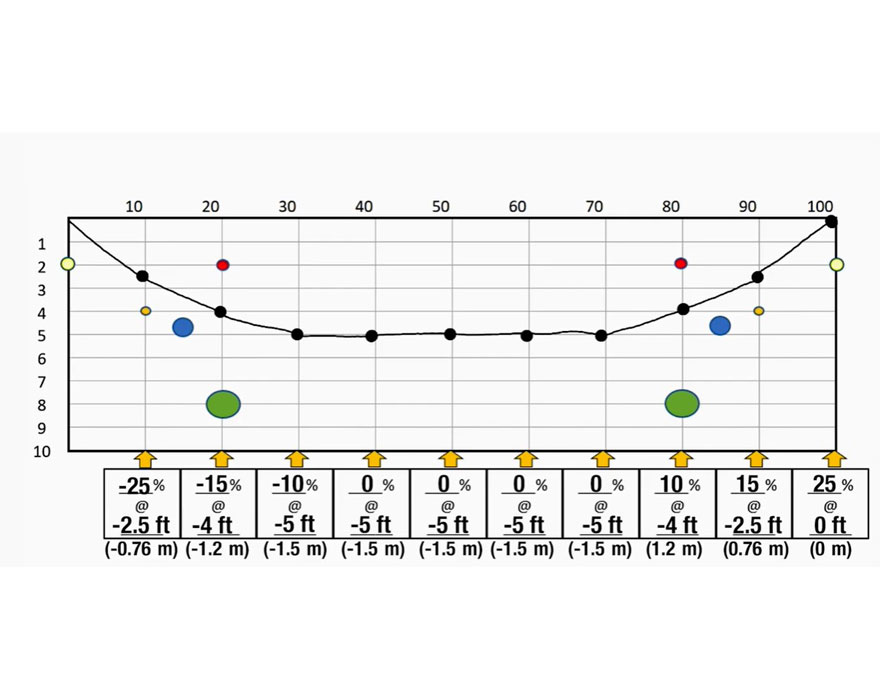
Drawing the last rod on the graph shows that at a positive 25% pitch you’ll exit the ground at the end of the 10th rod. And your HDD bore plan is set.
It is important to note that these numbers are an approximation. Other variables that can affect planning will be ground conditions, topography and HDD tooling.
Now that you understand what required information is needed, along with the quick math, you can create a bore plan for your next HDD jobsite. For a visual version of this information, check out the video below.
For more information and HDD training, contact your local Vermeer dealer.
Vermeer Corporation reserves the right to make changes in engineering, design and specifications; add improvements; or discontinue manufacturing at any time without notice or obligation. Please contact your local Vermeer dealer for more information on machine specifications.
Vermeer, the Vermeer logo, Equipped to Do More and Navigator are trademarks of Vermeer Manufacturing Company in the U.S. and/or other countries. © 2022 Vermeer Corporation. All Rights Reserved.